All Categories
Please Note: Shipments to the United States may experience delays because of the new regulations and interruptions due to the inspection at the U.S. customs. We appreciate your understanding and patience
Introduction
In this post you learn how to send and receive SMS by using a Sim800L module and an Arduino UNO. You can use this idea for many applications, including receiving data from specific sensor by SMS. Data could be your car’s or UAV’s location, Temperature and humidity of your city, heart rate of a patient and etc. Or you can enable some algorithms by sending an SMS. Enter a Sim Card to Sim800L, change the phone number in code and upload it to Arduino, make the circuit as explained below. Your circuit is ready for sending/receiving SMS (ready for sms tracking).
Requirements
You can download it’s datasheet from Sim800L Datasheet.

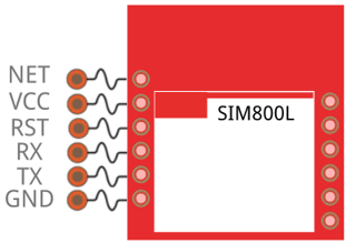
In this project we’re going to use NET, VCC, RX, TX and GND pins. You should connect an antenna to NET pin. The GND pin must be common with other GNDs in the circuit. For turning on the module connect VCC pin to 3.4 – 4.4 V. RX and TX pins are for receiving and transmitting data.
Sim800L has an LED with tree states: 1. Not blinking: It’s off 2. Blinking every 1 second: It’s on but it hasn’t made connection to network yet 3. Blinking every 2 or 3 second: it has made connection and it’s ready to send/receive SMS (and call).
You can use Arduino UNO. You can download UNO’s datasheet from https://datasheet.octopart.com/A000066-Arduino-datasheet-38879526.pdf .

Pin’s explanation
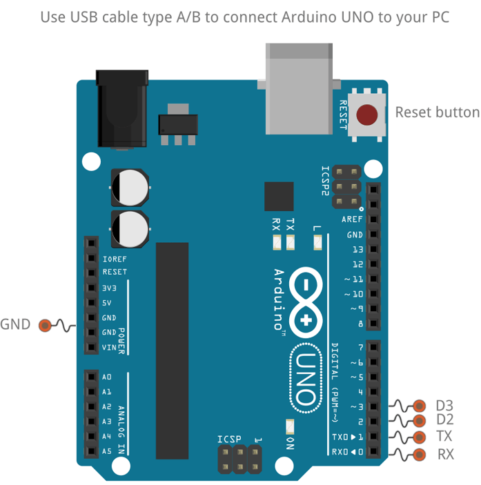
Use an USB cable A-Male to B-Male for connecting UNO to computer and an USB cable A-Male to Mini-B-Male for connecting NANO to computer.
Connect Sim800L’s VCC and ground to 3.4 – 4.4 V battery.
Connect Arduino’s ground to Sim800L’s ground.
Connect Arduino’s D2 and D3 to Sim800L’s TX and RX.
Hint: Arduino and Sim800L have different voltage level; So use 2 resistors to divide voltage. You can use a 10K and a 20K ohm.

SEND:
					//This code will send a text to specific phone number every minute

#include "SoftwareSerial.h"

SoftwareSerial sim800l(2, 3); // RX,TX for Arduino and TX,RX for Sim800L

void setup()
{
  sim800l.begin(9600);
  Serial.begin(9600);
  delay(1000);
  Serial.print((char)26);
  SendSMS();
}

void loop()
{
     delay(60000);
     SendSMS();
}

void SendSMS()
{
  Serial.println("Sending...");
  sim800l.print("AT+CMGF=1\r");                   //Set the module to SMS mode
  delay(100);
  sim800l.print("AT+CMGS=\"+86**********\"\r"); 	//phone number don't forget to include your country code"
  delay(500);
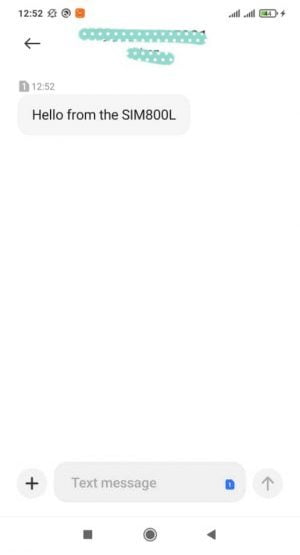
  sim800l.print("Hello from the SIM800L");		//This text will send to the phone number
  delay(500);
  sim800l.print((char)26);
  delay(500);
  sim800l.println();
  Serial.println("Sent.");
  delay(500);
}

Read More: New Parrot ANNAFI Specifications Released
Receive:
					//This code will show SMSes which receive to Sim800L

#include "SoftwareSerial.h"

SoftwareSerial sim800l(2, 3); // RX,TX for Arduino and TX,RX for Sim800L

void setup()
{
  sim800l.begin(9600);
  Serial.begin(9600);
  delay(1000);
  ReceiveSMS();
  sim800l.println("AT+CMGF=1");
  ReceiveSMS();
  sim800l.println("AT+CNMI=2,2,0,0,0");
  ReceiveSMS();
}

void loop()
{
  ReceiveSMS();
}

void ReceiveSMS()
{
  delay(500);
  while(Serial.available())
  {
    sim800l.write(Serial.read());
  }
  while(sim800l.available())
  {
    Serial.write(sim800l.read());
  }
}
No account yet?
Create an AccountNeed help?